API General Cure powder is a great medication to treat both internal and external parasites in tropical fish including discus.…
API General Cure powder is a great medication to treat both internal and external parasites in tropical fish including discus.…
Parasites are a natural components of all healthy ecosystems and all fish, including tropical Discus, can have internal and intestinal parasites.…
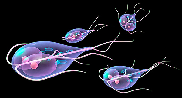
Spironucleus is a flagellate parasite that affects a large group of fish, including ornamental tropical species. Even though the Spironucleus is responsible…
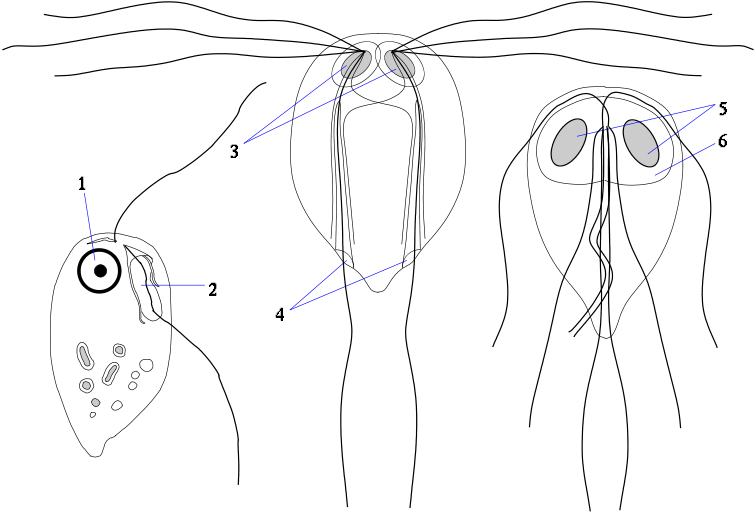
Hexamita is a flagellate protozoa that affects the gastrointestinal tract of ornamental fish. Protozoa are microscopic, single-celled organisms that may or may…
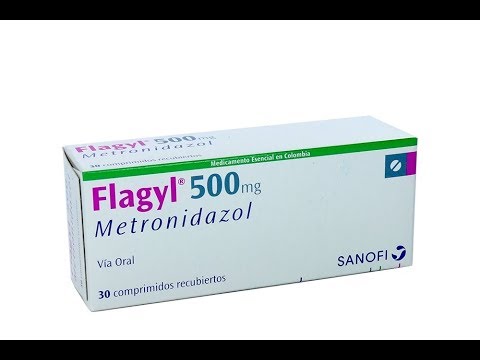
Metronidazole (MNZ) is a very popular and effective antiprotozoal medication in aquarium and ornamental fish industry which is used to…
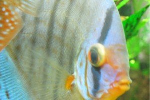
Popeye in fish also called exophthalmus, proptosis, exorbitism, exophthalmia, or exophthalmos is not a specific discus disease itself but describes a…
Hole in the Head (HITH) in fish, also known as Head and Lateral Line Erosion (HLLE), is a very common aquarium and tropical…
The main cause of death in most imported discus fish from east Asian countries such as Thailand and Malaysia is a…
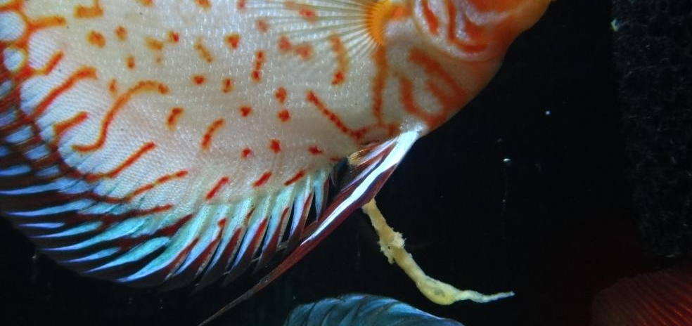
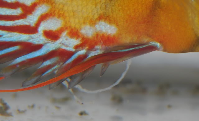
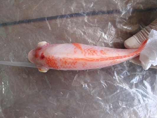
White feces in fish, also called white stringy poop, is a fairly common symptom in both freshwater and marine aquarium fish which not…
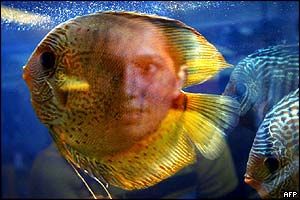
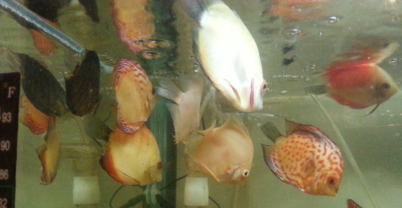
The first and most important part of Discus Keeping is to choose and select a good and high quality Discus…